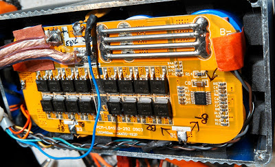
I was alarmed by the fact that after just 2 years, all three of these packs had appeared to degrade badly: Of the three, two of them had seen their original 6+ amp-hour capacity diminished to 2 amp hours or less (the third was at about half capacity) and their capacity was decreasing every time I checked them.
In response to this post I had several comments/suggestions (you may find them at the end of the original post, linked above) about what might explain the problems that I was having, including:
- Temperature variations. Very cold temperatures will dramatically reduce the available cell capacity, but these batteries were all tested at similar (room-like) temperatures.
- Perhaps I'd charged the cells to too-high a voltage and damaged them? I'd checked and found that the internal circuits prevented the cells from "seeing" voltages in excess to those noted in the manufacturer's recommendations. Considering the rather light usage (only a few dozen cycles) it seemed unlikely that they would suffer such damage so quickly even if they were abused a bit.
- Self discharge? Perhaps the protection circuits inside the battery were causing the packs to bleed down? Maybe the cells themselves were losing charge on their own?
More recently I finally got the time and inclination to disassemble one of my LiFePO4 packs and do a bit of looking.
Analysis:
First, I charged the pack by connecting it to a 14.6 volt, current-limited (500 mA) source. After the current dropped to nearly zero (overnight) I disconnected it from the charger and let it sit for a week or so to let the cells "settle out" and attain a steady-state voltage. Upon disassembly to the point that I could measure the voltage across each individual cell I found that they were fairly close - within 0.1-0.15 volts or so - not radically different, but still a bit more than I would have expected.
I then put the battery pack on my West Mountain Radio CBA-II battery tester and did a capacity test which subjected it to a constant 2 amp load while graphing and integrating the results. As expected, this pack, which had measured at about 6 amp-hours when it was new, now measured less than 2 amp-hours.
Upon measuring the voltages across the cells in this discharged state the precise nature of the problem became clearer: Several of the cells were in the 2.8-3.1 volt area but one cell was at about 2.4 volts and it had no doubt been lower (probably down to 2.0 volts) when it was under the load of the tester!
Did I have a bad cell?
The first thought was that this indicated a cell that had gone bad, but before I was about to condemn anything, I needed to do a bit more testing.
I charged the pack again and when complete - but still while on the charging voltage - I checked the cell voltages and saw that at least one of them was at about 3.9 volts - just at the voltage where the protection circuit would disconnect the charging current for the entire string - and this meant that charging would no longer proceed. I then set an adjustable voltage supply to precisely 3.65 volts and connected it across each cell, in turn, for several hours (until the charging current dropped off) to assure that every cell was fully charged.
Interestingly, the cell that I had thought might be bad (the one at about 2.4 volts) took a charge - and then kept taking a charge for several hours before the current tapered off. In contrast, the cell that had been at the highest voltage immediately reached full charge as indicated by the current dropping off quite soon after I'd applied it.
Cell imbalance and how it can cause apparent loss of capacity:
This behavior implied a problem that was different from what I'd expected: Gross cell imbalance.
One vexing problem with any system of series-connected cells (e.g. a battery) is that since not all cells are exactly the same, one will inevitably discharge sooner than the others. on "primary" batteries, this isn't too much of a problem since being non-rechargeable, a few percent of difference between cells won't have too much effect over the pack as a whole. on a "secondary" battery - the types that can be recharged - this can be an issue, especially if the problem accumulates over a number of charges.
Perhaps the most notable of deleterious side-effect of cell imbalance is that experienced in NiCd packs where the premature discharge of one cell results in its effectively being charged backwards and a chemical process occurs in which dendrites (metallic hairs) grow, reducing its capacity and in severe cases, shorts the cell and/or causes it to self-discharge very quickly. In this case, this cell - already weakened due to dendritic damage - will be the first to discharge the next time it is used and this will happen again, causing even more degradation!
In the case of a Lithium pack, this unintentional "reverse charge" doesn't occur as there are (supposed to be) circuits that prevent any of the cells in the pack from being discharged too deeply by disconnecting the entire battery from the load - something that (in Lithium chemistry) can cause permanent damage. This same circuit also does something else: If, while charging, the voltage on one or more cells exceeds a particular threshold (typically 4.2 volts for most conventional Lithium-Ion cells) the entire battery is disconnected.
For the LiFePO4 battery, the chemistry is a bit different. While the "low voltage disconnect" of these cells is comparable to that of some conventional Li-Ion chemistries (2.0 volts) the high-voltage disconnect on the particular LiFePO4 cells that these packs contain is 3.95 volts maximum.
Note: The nominal "full charge" voltage for these particular LiFePO4 cells is normally 3.65 volts. As is typical for any rechargeable cell, the voltage on a cell immediately decreases when the charging source is disconnected.
What seems to have happened was this:
- When the battery pack runs down: One cell reaches 2.0 volts, the internal circuit disconnects the load. Other cells have probably not reached 2.0 volts and still have remaining charge.
- When the battery pack is charged: One (but not the same one as above) cell reaches 3.95 volts, the internal circuit disconnects the charging current. Inevitably, the other cells that did not reach this voltage and were thus not as fully-charged.
- When the battery is discharged the next time. The cell(s) that didn't get fully charged the last time will likely be the one(s) that discharge first: When that happens, the load is disconnected, but the other cells will still have charge on them.
- When the battery is charged again. Those cells that had the most charge will reach the maximum voltage first, leaving the more-discharged cells with a less-then-full charge.
- This process repeats. The disparity between those cells that are fully charged and those that were not fully charged will increase. Because the overall capacity of the pack is dictated by the weakest cell - in this case, the one that has the least amount of charge - the apparent capacity of the battery pack will gradually decrease.
 |
||
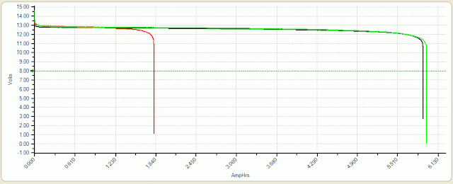
| Figure 1: One of the LiFePO4 battery packs when nearly new (black) and after 2 years (red) there is very clearly a loss of available capacity! Click on the graph for a larger version. |
It should be noted that the load test current in the graphs on this page were 2 amps, much higher than the "20 hour rate" at which battery manufacturers typically rate batteries. Because of this, the tested capacity was somewhat lower than the pack's official 6+ amp-hour rating.In each case you can see that near the end of the discharge curve, the battery voltage starts to droop - and then is abruptly cut off by the protection circuit when one or more cells drops below 2.0 volts. What I should have noticed was that the overall voltage before the curve started to get steep was actually lower when the pack was "good" than it was when its capacity had diminished. What this indicated was that when the battery pack was newer and performing better (black trace) all of the cells' voltage were dropping more nearly in unison while on the red trace, we don't see that gradual drop to nearly the same extent implying that, perhaps, just one cell was dropping out sooner.
Equalizing the cells - the result:
As mentioned above, I individually charged the cells using a regulated, current-limited power supply that was set to 3.65 volts and then individually tested each cell's amp-hour capacity. I was pleased to note that every cell seemed to be fairly close to its rated specifications and, as I now suspected, the cells that had been noted to have discharged first when the pack as a whole was tested were, in fact, those that had slightly lower capacity than the others by 5% or so.
As described abive, I then recharged the entire pack and then topped each cell off, individually, to 3.65 volts, and then re-tested the entire pack again:
Figure 2 shows the result of that test. As can be seen, the capacity of the battery pack after having equalized the cells (the green trace) is slightly better than it was when it was brand new!
Clearly, there was a problem to be solved: How do I keep this - and other - LiFePO4 battery packs "equalized" and still have them be practical and safe to use. Here are the points to consider:
- I did not want to remove the battery's built-in protection circuit as it takes very few cycles of gross over/under voltage before one permanently wrecks Lithium-Ion cells. While LiFePO4 cells are considered to be (more or less) "intrinsically safe" when compared with conventional Lithium-Ion cells, that just means that they are less like to catch fire/explode if mistreated, not that they won't degrade quickly!
- A practical method of charging the battery pack and maintaining equalibrium of the cells within. What this meant was that I was not going to disassemble the pack every time I wanted to charge it so that I could get at each cell!
- Charging/equalizing should be relatively simple and convenient. This goes with the above and it would imply a simple box that I could connect to the battery while charging, when I wanted to equalize the cells.
Instead, I decided to modify each pack, bringing out connections from each individual cell so that the voltages could be monitored and controlled during "normal" charging of the pack. To do this, I added a short cable with a 5-pin DIN connector which provided the points needed to which I could connect an external box with which the cells could be equalized when charging. What this also meant was that I needed to construct only one external device to monitor and control the voltage on three LiFePO4 battery packs that I had!
A charge monitoring and control circuit:
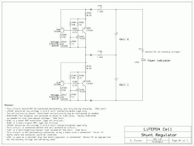
Please note that the diagram in Figure 3 represents what would be required for just a 2-cell (nominally "6 volt") LiFePO4 battery: one would simply replicate the circuits as needed for as many cells as the battery pack contained, connecting them in series as shown in the diagram. For the discussion below, we'll generally refer to the parts in the circuit connected to Cell 1 which are numbered with parts designations in the "100's".
How it works:
As noted above, wires are connected to the cells inside the battery pack and brought out through a cable that is separate from the main power connector. I used a 5-pin female DIN connector as it had precisely the number of connections needed: Battery - (minus) and the + (positive) terminals of each of the four individual cells.
You will note that in the diagram there are devices marked F101 and F201 which are 1 amp, self-resetting thermal fuses located at the point where the wires connect to the cells (or protection circuit) inside the pack. These are extremely important as an accidental short-circuit of one of the wires emerging from the pack could result in burns or a fire without its presence as the cells will easily supply enough current to burn the wires open! Adding these devices is a cheap way to make the modification safe and should a short occur, simply fixing the problem (removing the short) will cause the fuse to automatically reset when it cools down - more on these devices later.
The heart of the circuit is U101, a TL431 shunt regulator - a part that may be found in nearly every PC power supply. This device is essentially a programmable Zener diode: If the "adjust" terminal is more than 2.495 volts (nominal) above the anode terminal, it will conduct via the cathode. The values of R103 and R104 are chosen so that if more than 3.65 volts appears between the "top" of R103 and the bottom of R104 (which is also connected to the anode of U101) more than 2.495 volts will appear on its adjust terminal and the device will turn on.
When U101 turns on, it will start to "pull down" on the base of Q101, a PNP power transistor, which will conduct, amplifying the effects of U101 and start drawing current through R101 (R102 keeps Q101 turned off otherwise.) Were it not for the presence of R101, a 0.25 ohm resistor, the "knee" of this conduction would be extremely steep, but this resistor gives the circuit a bit of elasticity (a bit of range over which the current will go from nearly zero to maximum) and also assure that the circuit will not oscillate. With the parts in the diagram, a current of about 200 milliamps through the shunt regulator - plus the finite gain of U101 - will result in a clamping voltage on the cell of around 3.75 volts, not including the effects of the resistance of the wire/connector that runs to each cell within the battery.
As a convenient indicator that the U101 circuit is actively shunting current from the cell, Q102 detects when U101 is "pulling down" on the base of Q101 and turns Q102 on, causing LED101 to illuminate. Q102 and associated components (LED101, R105, R106) are optional if you don't need an indication of a particular cell reaching full charge.
Finally, there is also a simple circuit consisting of R1 and LED1 that is across the entire battery. The sole purpose of this is that of an indicator to show that this circuit is connected to a battery and serve as a reminder that it should be disconnected when charging is complete!
Comments on parts and construction:
As noted above, by cascading multiple copies of this circuit one may apply them to as many cells as needed - whether it is just a pair of cells, or many more than that. Because my LiFePO4 packs were "12 volt" types with 4 cells in series, I cascaded 4 of the circuits together, building it on a small piece of perforated prototype board as shown in Figure 4.
The type of prototyping board that I used has a small copper ring around each hole making construction much easier, more rugged and more durable.
I do not currently have plans to produce a circuit board for this project, but let me know if you do as it might be of interest to others.
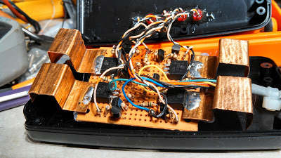 |
| Figure 4: A 4-cell Cell equalizer circuit built on perforated prototype board. Click on the image for a larger version. |
The TIP32A PNP power transistors are of the TO-220 type (with metal tabs) and were chosen simply because I had a lot of them onhand, but practically any PNP power transistor could have been used - but I would not recommend Darlington types due to possible emitter-base voltage limitations. As can be seen in Figure 4, pieces of copper, bent to fit within the box and to increase surface area - were soldered to the tabs of these transistors to improve power dissipation.
With the heat sinks shown and with the box put together, the unit can easily withstand 200 milliamps of shunt current on each of the four sections without causing excessive thermal stress of the components inside from the 3-4 watts total heat generated. If much more shunt current capacity is desired, larger heatsinks and/or better ventilation - or perhaps connecting the transistor's tabs to a metal box (making sure that their heat sinks were electrically insulated) - would be recommended along with the decrease of the value of R101. Practically speaking, by proper choice of the transistor, the value of R101 and heat sinking one could design this sort of circuit to accommodate practically any amount of shunt current!
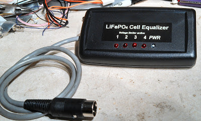
In the lid of the box I drilled some holes and used cyanoacrylate ("Super") glue to to hold the LEDs in place temporarily (overnight) and then used clear epoxy to more-permanently secure them into position afterwards. Because this shunt regulator was intended for 4 cells, there is a red LED for each of the shunt regulators to indicate its "full charge" status plus a fifth, bright blue LED as an indicator to show that the unit is, in fact, connected to a battery a serves as a reminder to disconnect it when charging is complete.
Figure 5 gives a view of the completed shunt regulator showing the short cable and the male DIN connector that is connected to the mating connector on the battery. As the label indicates, the five LEDs on the front show the full-charge status and whether or not it is connected to power. It is worth noting that when they were installed, the LEDs weren't fully pushed to protrude through the front panel. If they had pushed all of the way through the hole, they would have stuck out too far and would have risked being accidentally broken loose and pushed back into the box during handling.
Comments:
- A "simpler" way to do this: In theory, one could parallel a fairly low-value resistance across each cell - say, a 22 ohm, 1 watt device - and achieve equalization with this value of resistance equating to about 165 milliamps of current at 3.65 volts. Eventually - after, perhaps 36-48 hours for a pack of this size - the cells would gradually equalize their charges - and the lower the resistance, the more quickly equalization will occur. If this is done, resistors with the appropriate power rating should be used and they should all be of equal value and, of course, they should be disconnected immediately after charge has been completed, just before the charging voltage is disconnected
- For other than LiFEPO4 cells: For different types of cell chemistry one would choose the values of R103/R104 as appropriate (see the data sheet for the TL431 for more information.) Note, however, that this circuit will simply not work for voltages much less than 3.0-3.2 volts! If, for example, one wanted to regulate "2 volt" lead-acid cells you could use this sort of circuit directly, but multiple regulators could be placed across pairs of cells (and the shunt voltage set to approximately 4.55 volts) in an interleaved manner and achieve the same effect.
- Make sure that all circuits are equal: Once constructed, the clamping voltage of the individual cells' circuits should be checked at the same current, say 200 mA and if necessary, adjust the value of R103 or R104 to make all of them equal: All cells being within 50 millivolts (0.05 volts) of the target voltage should be more than adequate. It's worth noting that normal variations in the resistor values (particularly if 5% tolerance parts are used) as well as variations among TL431's can cause voltages to differ slightly.
- Where to find the TL431: As mentioned above, the TL431 can be found in nearly every PC-type power supply made. If you have some scrap power supplies laying around, you may be able to find enough of these devices for your project! The devices that I used are in TO-92 packages and look just like a transistor. Different manufacturers have their own prefixes, but if you see a part that looks like a transistor and ends in "431", it's probably a TL431! If you don't want to dig around in old power supplies, these chips are readily available from many distributors at well under US$1.00 each.
Modifying the battery packs:
Because of the high currents involved, there is some risk of burns/fire should connections be accidentally shorted.
Do not perform this sort of modification unless you know exactly what you are doing!
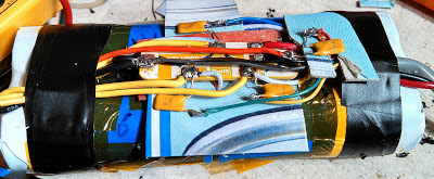
One of the more critical aspects of this projects was safely modifying the battery pack. As noted above, the wires connecting to the outboard charge equalizer have current limiting on them in the form of (approximately) 1 amp, self-resetting thermal ("PPTC") fuses that are located inside the battery's case.
For a Wikipedia article on these devices, click on this link.
Again, the fuses are necessary safety components to prevent burns/fire should the added connection(s) be accidentally shorted out!Some builders may not be familiar with these self-resetting fuses so a few words of explanation are in order.
Typically resembling small, yellow disk-ceramic capacitors, these devices are actually specially-designed thermistors: If the current through them exceeds the design threshold, they will get hot (but not too hot!) and their resistance will skyrocket. When in this "tripped" state, enough current will still flow through them (typically 5%-15% of the rated trip current) to keep them "warm" and in the "tripped" condition with a high resistance. once the fault has been removed, they will cool down and reset themselves as their internal resistance returns to normal.
These devices are readily available from electronics suppliers like Digi-Key, Mouser and Jameco (to name but a few) and aren't all that much more expensive than normal one-time" fuses. Available in current ratings from below 100 mA to 10's of amps, the 1-amp rating noted is a suggestion: The devices that I used were actually rated for 1.1 amps of "holding" current, but anything in the range of 0.6-1.5 amps would have been just fine in this application as that current range will keep the wire from burning up in the event of a short, yet be enough to handle the expected shunt current.
As mentioned, when "blown", these self-resetting fuses do not completely stop the current flow, but reduce it to a "safe" level. What this means is that should the wire be shorted out indefinitely, the affected cell(s) will eventually be discharged, but you aren't likely to set anything on fire - and this is particularly important since our connection to the cells must bypass the protection circuits within the battery pack!
Of course, if you wish, you can substitute "normal" (one-time) fuses. While these have the disadvantage of being usable only once, they do have the advantage that if a wire shorts and the fuse blows, current completely stops and you won't likely run down - and possibly damage - a cell.
The other pack (Figure 7) was constructed in the traditional way: Series-parallel connected cells (four pairs in series in a "4S2P" configuration) to get the desired voltage and capacity and as such, the modification was much easier to accomplish.
To find the connections to the individual cells, the battery packs were (carefully) disassembled and the locations of the individual wires traced. Using a voltmeter, find the "bottom" cell of the pack (usually marked "B-" and using it as a refrence, locate and mark each subsequent cell by the successive increase in voltage. Often, these other cells are marked "B1", "B2", etc. with the "top" cell marked with "B+". Note that it is not necessary to put a fuse one of the "end" leads (the B+ or the B-) - but I usually omit the fuse at the B- lead. It is safe to do this as any possible combination of wires being shorted will always involve at least one fuse in the leads!
Note: On the battery packs, female DIN connectors are used to prevent accidental contact with the voltages that are always present on these pins.
Using the Shunt Regulator/Equalizer:
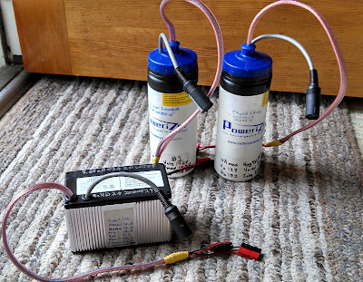 |
| Figure 8: The three modified LiFePO4 packs, the extra wire/connector being clearly visible. Click on the image for a larger version. |
Through experimentation, I determined the precise voltage at which all four shunt circuits would conduct at 150-200 milliamps - which turns out to be about 14.72 volts for the device that I'd built. When the current from the power supply settles down this amount for a few hours I know that the voltages on the cells are equalized and that the battery should be removed from the charging voltage.
Using it for the first time or on a battery that is badly unequalized:
The first time I used the device on a battery pack that was known to be badly out of equalibrium for which I had NOT already charged each cell individually, it took 24-36 hours for all of the cells to come to equalibrium. What happened was that once the "most charged" cell achieved its target voltage, the shunt regulator took over for that/those cell(s) and the others were charged by the "excess" current being passed around the fully charged cell(s).
Because this shunt current was only on the order of 100-200 milliamps, it took quite a while for these other cells - some of which were still at only 20-25% charge - to be fully "topped off" at this rather low current.
Subsequent charges:
One does not need to use this device every time a battery is charged!
It takes several cycles (and time!) for the cells within the battery to "drift" apart and fall out of equilibrium so one could probably get away with using it only every 6-12 charges (or 3-6 months, whichever is sooner) and still maintain good charge capacity on the battery pack.
When done:
Once the charging has been completed, the battery should be disconnected from the power supply used to charge it and the equalizer circuit should be disconnected.
This equalizer circuit, when the voltage(s) on the cell(s) are below the clamping threshold, doesn't draw much current - somewhere in the 3-5 milliamp range - so it is not likely to discharge a pack of this size very quickly. If this were were left on a battery connected across a small solar panel, for example, its contribution to the discharge of the battery would be negligible.
Final analysis of the problem:
One of the ways to most-quickly "kill" any Lithium-Ion based cell is to maintain it at a full charge voltage all of the time: Best longevity is generally obtained if it is kept it in a relative state of discharge (30%-60%) and charging it fully only just before you need it. Keeping it in a state of "partial charge" reduces the rate of inevitable degradation that occurs over time due to the intrinsic chemical decomposition. one must also be aware that allowing the voltage on any cell of a lithium-ion battery to drop below 2.0 volts can also damage or make it unusable: on some packs, if a cell voltage drops too low the protection circuit will actually prevent charging.
With this in mind, I generally keep my Lithium-Ion power packs in partially-charged state - or at least never leaving it on a charger for long periods - and have had good luck over the past 15 years or so that I have been applying that principal, typically getting at least 5 years out of the pack before its capacity drops below about 60% of its design.
So was the intent when I got these new LiFePO4 packs: I would top them off occasionally - usually just before using them - and when I was done, I'd typically leave them in their partially-charged state. Apparently, this strategy won't work. What to do, then, other than either leave them on a float voltage all of the time or build a circuit like this and make sure that the individual cells are fully charged and equalized?
Again, I'm reluctant to put these batteries on a charger, set to 14.6 volts (3.65 volts/cell) and just walk away. In theory, if I did do that they would eventually reach equilibrium as the fully-charged cells, having gotten above their maximum voltage threshold would occasionally self-discharge just below it and allow charge current to be applied across all the cells in the pack, if even occasionally, for a brief moment. Again, doing this will inevitably reduce the overall lifetime of the battery, but perhaps this is an acceptable tradeoff for you.
What the "protection" circuits current found in batteries should really have is a more intelligent charge management capability in that if one cell was at a higher potential than one or more of the others, current would be shunted around it, allowing the other cells to equalize. Alas, that's not the way they work, hence this need/purpose of this project!
Why don't other LiIon battery types experience this "inequality" problem more readily? Part of this has to do with the fact that many of them (e.g. batteries in laptops) are typically "stored" in the device and kept at full-charge voltage all of the time and will eventually equalize.
Lead-acid (e.g. car) batteries along with NiCd and NiMH cells are less-often subject to this problem (inequality related to charge/discharge rather than cell degradation) mostly because they can be subjected to a degree of abuse (overcharging) without worrying too much about damage, and this allows all of the cells to equalize. Again, since you can't do this to Lithium-ion cells and expect them to last a long time, this "purposeful overcharge" isn't really an option!
(Note: There are equalization techniques applied to various types of batteries - namely lead-acid - but those will not be covered here.)
Results:
How do the batteries test now, after more than 2 years of ownership, before equalization, new and after equalization? The graph in Figure 9 tells the story:
As you can see in Figure 9 there was significant degradation of capacity as the cells drifted apart from each other, rapidly decaying in just a few months (5/12 to 9/12). Packs #1 and #2 are identical, originally consisting of a pair of LiFePO4 packs connected in parallel at the outputs of the protection board (one of these was depicted in Figure 6) while the "Metal" pack had just one protection board with the cells originally connected in series-parallel format.
All three of these packs were used approximately equally, but it's interesting to note that the metal-cased pack seems to have degraded far less: Was this due to differences in usage, or because of the way the cells were configured? It could be that the "metal" pack with its "2P4S" configuration (rather than the original "4S+4S" format of the water bottle batteries) the rate-of-change of their respective states of charge from the pairs of cells in parallel caused a slower rate of degradation.
It's also interesting to note that in the case of the metal pack and water bottle #2, the capacity after equalization was actually higher than it was when new, indicating that when it was "new", the cells were already drifting apart and that the cells' capacities probably haven't degraded much in the 2+ years since they were made!
So, what do I think about LiFePO4 cells now?
I'm more than willing to concede that, perhaps, there is something to this longevity of LiFePO4 cells after all. As can be seen above, once the packs were equalized the cells seem none the worse for wear after several years have passed along with a degree of abuse.
What about this (apparent) propensity of the cells to drift apart? It might be interesting to have another pack that is left on charge" for long periods of time to see if it will equalize itself and/or if it degrades at an accelerated rate. It could also be that newer protection circuits and cells are more likely to maintain a closer charge state than these (now) older packs. Perhaps other brands of batteries would be less susceptible to this problem.
Would I get more LiFePO4 batteries in the future? Yes, now that I know that I should be on the lookout for a problem like this!
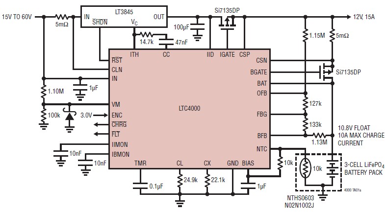
리니어의 단일셀 리튬인산철 배터리용 고효율 파워 관리 및 충전기
리니어 테크놀로지 코리아는 자동 고효율 파워 매니저이자 아이디얼 다이오드 컨트롤러 및 리튬인산철(LiFePO4) 배터리 차저인 LTC4098-3.6을 출시했다고 밝혔다. 이 제품은 산업용 미터, 미디어 플레이어, 디지털 카메라, PDA, 개인용 내비게이터와 같은 휴대용 기기를 비롯해 특히 높은 피크 출력이 높고 안전이 중요한 기기에 사용된다. LTC4098-3.6의 스위칭 토폴로지는 5V 어댑터, USB 및 LiFePO4 배터리 등 다중 소스간에 전력 분배를 원활하게 관리하는 것은 물론, 시스템 부하에 우선적으로 전력을 제공하는 파워패스(PowerPath™) 제어 기능을 제공한다.
자동차 및 기타 고전압 어플리케이션의 경우, LTC4098-3.6은 리니어 테크놀로지의 외장형 스위칭 레귤레이터에 연결되어 고효율 고전압 전원 경로를 제공할 수 있다. 온보드 스위칭 레귤레이터는 USB 호환성을 위해 입력 전류를 자동으로 제한할 수 있다. 저전압 입력 및 고전압 인터페이스 모두 어플리케이션에 최대 전력을 공급하기 위한 배트 트랙(Bat-Track™) 최적화 충전 기능을 제공한다. 또한 5V부터 38V의 높은 입력 공급 (60V 절대 최대 전압)을 가지는 고전력 밀도 어플리케이션에서 열을 감소시킨 것이 특징이다.
LTC4098-3.6은 저전압 입력에서 최대 66V까지 과전압 보호(OVP) 회로를 제공하여 외장 NFET/저항만 있으면 되기 때문에 갑작스런 고전압 인가로 인한 손상을 예방할 수 있다. LTC4098-3.6의 “인스턴트 온(instant-on)” 동작은 완전히 방전된 배터리라도 플러그인에서 시스템 부하 전력을 보장한다. 온보드 아이디얼 다이오드는 입력에서 전력이 불충분할 때 VOUT 에 앰플 전력이 항상 공급되도록 한다. LTC4098-3.6의 아이디얼 다이오드 컨트롤러는 옵션 사항인 PFET의 게이트를 구동하는데 사용될 수 있으며, 배터리 쪽의 임피던스를 30mΩ이하로 감소시킨다.
LTC4098-3.6의 완전한 기능을 갖춘 단일셀 LiFePO4 배터리 차저는 0.5%의 높은 정확도를 제공하며, 3.6V로 미리 설정된 충전 전압을 가지고 있다. 1.5A의 충전 전류는 일반 어댑터 전원 공급 시 사용 가능하지만, USB 파워 서플라이에 연결될 때에는 부하 전류가 USB 부하 스펙을 지키면서도 USB 포트로부터 공급 받는 전류를 초과할 수 있도록 한다.
고속 충전을 위해, 이 제품의 스위칭 입력 단계는 USB에서 공급 받는 2.5W의 거의 대부분을 시스템 전류로 변환시켜 500mA로 제한되어 있는 USB 포트로부터 최대 700mA를 제공할 수 있도록 한다. 뿐만 아니라 이 차저는 온도 제한, 자동 재충전, 자동 충전 종료 기능의 독립형 동작 및 1시간으로 고정된 안전 타이머, 불량 배터리 셀 검출 및 0°C~ 60°C 온도 조건에 따른 충전을 위한 써미스터 입력도 포함하고 있다. LTC4098-3.6의 또 다른 기능은 디바이스가 실행 중지된 USB 포트와 연결됐을 때 배터리가 소모되는 것을 방지하기 위해 LDO를 정지시키는 것이다.
LTC4098-3.6은 로우프로파일(0.75mm) 20핀 3mm x 4mm QFN패키지로 제공되며, -40°C~85°C의 온도범위에서 작동하도록 되어있다.
